- All
- Product Name
- Product Keyword
- Product Model
- Product Summary
- Product Description
- Multi Field Search


400M Type I,II,III Different Frequency Analog Optical Fiber Integrated Power Amplifier 10W
UZIWAVE
| Quantity: | |
|---|---|


Dual-access local and remote monitoring – Features onboard USB (local) and RJ45 (remote) ports, each shipped with factory-tested cables (dual-USB and 2m RJ45) for out-of-the-box deployment.
Universal AC input with low power draw – Accepts 110–220V wide-range AC power while consuming ≤180W, ensuring compatibility across different grid environments.
Outdoor-ready hardened enclosure – Rated IP65 for weather resistance, operates from -25°C to +55°C, and includes a customer-specified lightning arrester for added electrical protection.
TETRA-optimized RF performance – Provides 20W output power with ≤5μs transmission delay, ≤5dB noise figure, and third-order intermodulation (IM3) ≤-45dBc for critical trunked radio applications.
Independent UL/DL gain and ALC control – Both uplink and downlink support ≥25dB gain adjustment and ≥20dB ALC range, with gain flatness within ±1.5dB across attenuation steps.
Rugged mechanical and visual indicators – Housed in a 500×440×187mm chassis (≤28kg) with front-panel power, operation, and alarm LEDs, plus an LP20 power socket for secure AC connection.
Product Name:
1. 450M Same/Different Frequency Analog Optical Fiber Integrated Power Amplifier 10W
2. 400M Type I Different Frequency Analog Optical Fiber Integrated Power Amplifier 10W
3. 400M Type II Different Frequency Analog Optical Fiber Integrated Power Amplifier 10W
4. 400M Type III Different Frequency Analog Optical Fiber Integrated Power Amplifier 10W
Note:
• For the above four types of power amplifiers, the detection range requirement for uplink input power detection is: -100~-60dBm
Items: | Uplink (UL) & Downlink (UL) Specifications: | Note |
Frequency Range: | 1. 450M: a. UL:458M±1MHz b. DL:468±1MHz/458±1MHz 2. 400M Type I a. UL:403.7±0.5MHz b. DL:413.7±0.5MHz 3. 400M Type II a. UL:413.2±0.5MHz b. DL:423.2±0.5MHz 4. 400M Type III a. UL:408-409MHz b. DL:418-419MHz | |
Maximum Output Power (dBm) | 1. UL:0±1 2. DL:40±1 | |
Output Power Detection Range (dBm) | 1. UL:-40~0±1 2. DL:20~40±1 | |
Max Gain: | 1. UL:60±1dB 2. DL:60±1dB | |
Gain Adjustment Range: | 1. UL:≥30dB 2. DL:≥30dB | Software- adjustable, adjustment range (0- 30dB) |
Gain Adjustment Step: | 1. UL:≤1dB 2. DL:≤1dB | |
Gain Adjustment Error: | 1. UL:≤±1.5 dB 2. DL:≤±1.5 dB | |
Automatic Level Control (ALC): | 1. UL/DL: When the repeater operates at maximum gain and maximum output power: • If the input signal level increases by ≤10dB, the output power shall remain within ±2dB of the maximum output power; • If the input signal level increases by >10dB, the output power shall either remain within ±2dB of the maximum output power or the output shall be turned off | ALC requires software adjustment, with an adjustment range of (30~40dBm) and a step size of 1dB |
Spurious Emissions: | 1. UL/DL:Dual-tone ALC activation test is required • In-band: 9 kHz-1 GHz, ≤-36dBm/100kHz; • Out-of-band: 1 GHz-12.75 GHz, ≤-30dBm/1MHz | No spurious signals shall exist within the 10dB range from ALC activation and the 5dB back-off range |
Uplink Limiting | When the uplink input is -10dBm, the uplink output shall be ≤0dBm | |
In-Band Ripple: | 1. UL/DL:≤1.0 | (p-p) |
Noise Figure: | 1. UL:≤2dB 2. DL:NONE | |
Squelch Threshold (dBm) | 1. UL:−92~−72 2. DL:NONE | |
EVM: | ≤5% (Peak-to-Average Power Ratio 10.0dB) | |
VSWR: | UL/DL:≤1.4 | |
Delay (μs) | ≤1 | |
Intermodulation (dBc) | ≤-36 | |
Baud Rate: | 9600 | |
Passband Characteristic: −3 dB Bandwidth | > f(0)±1MHz | |
Filter Isolation: | Filter Isolation |
Power Supply: | 13.8VDC, ≤5A | |
Port Impedance | 50Ω | |
Operating Temperature: | -40~55℃ | |
Operating Humidity | 95%(40℃ | |
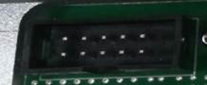
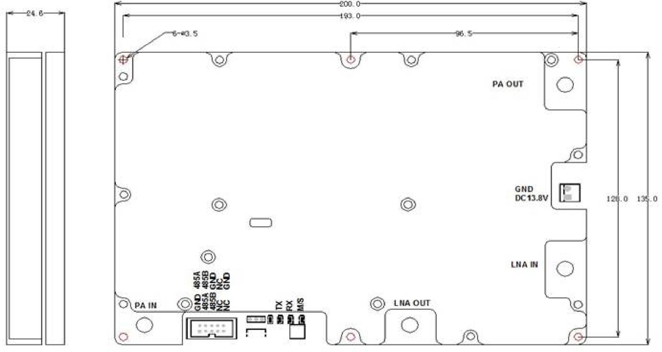
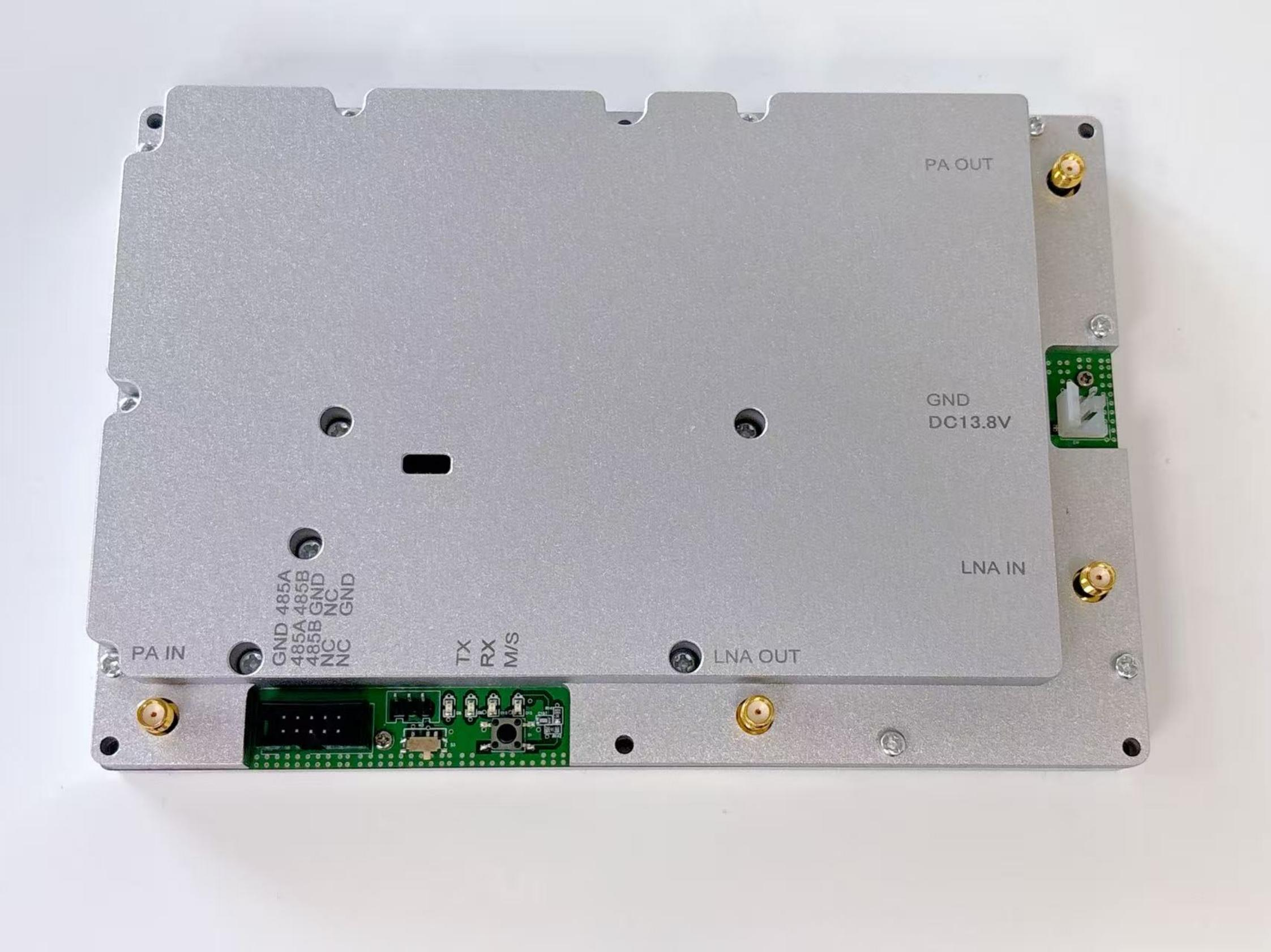
Monitoring Functions: | 1. For the wiring diagram of the monitoring port, refer to the outline dimension drawing; RS485 interface communication a. Settings: switch, gain; b. Query: module status (including power amplifier status, over-power alarm, over-temperature alarm), power amplifier temperature, power amplifier ATT value, detected forward power; c. Over-power alarm: alarm when the power exceeds the maximum output power by +2dB; d. Over-temperature alarm: recommended threshold is +85℃; alarm is triggered when the detected temperature exceeds +85℃, and the power amplifier is turned off simultaneously, then turned on at +65℃; e. Power amplifier temperature detection: the detection range shall include but not be limited to -25℃~+85℃, with a detection accuracy of ±3℃; f. Forward power detection: the detection range shall be greater than 20dB, with a detection accuracy of less than ±1dB; | |
Connecters: | SMA-female | |
Mechanical Dimensions: | 220*135*26 |
Other Mandatory Test Items:
1. When the downlink is in normal operation, the downlink operation indicator light shall stay on continuously.
2. When the downlink outputs full power, with the uplink threshold set to -92, the uplink indicator light shall not turn on.
3. The main/standby switch should be able to switch normally.
1. Overpower Alarm
An alarm is triggered when the actual output power of the power amplifier module exceeds the rated power by 2dB; the alarm threshold can be set via software with a dynamic range of 20-
40dBm and a step size of 1dB.
2. Over-temperature Alarm
An alarm is triggered when the internal temperature of the module exceeds +85℃; the power amplifier output is turned off when the temperature exceeds +90℃; the power amplifier
resumes operation after the temperature drops below +65℃ . The alarm thresholds can be set via software with the following ranges: alarm temperature 20-85℃; shutdown temperature 25- 90℃ (must be at least 5℃ higher than the alarm temperature); recovery temperature 0-75℃
(must be at least 5℃ lower than the alarm temperature); with a step size of 1℃ .
3. VSWR Alarm
a. The test is valid when the output power is greater than 20dBm;
b. An alarm is triggered when the reflection at the power amplifier output port is excessive and the VSWR exceeds 3:1;
c. When connected to a 1.5 VSWR load, the displayed VSWR value should range from 1.3 to 1.7;
d. When connected to a 2.0 VSWR load, the displayed VSWR value should range from 1.5 to 2.5;
e. When connected to a 3.0 VSWR load, the displayed VSWR value should range from 2.0 to 4.0;
4. RF Switch
When set to "On", the squelch switch is active; when set to "Off", the LNA cannot be turned on even if the input signal is greater than the squelch threshold.
5. Power Amplifier Fault Alarm
This alarm is triggered when: the power amplifier output is below 20dBm (with squelch
threshold enabled, no alarm if disabled), or the output power (dBm) ≠ input power + gain - attenuation, or any other alarm among VSWR alarm, over-temperature alarm, and overpower alarm occurs.
6. LNA Fault Alarm
This alarm is triggered when the LNA output is below -35dBm (with squelch threshold enabled, no alarm if disabled), or the output power (dBm) ≠ input power + gain - attenuation.
7. Same-frequency Priority
Downlink priority: When the module is in same-frequency mode (or same/different frequency mode), the uplink channel is turned off when there is a downlink signal output.
8. Master-Slave Switching
a. There are two power amplifier modules inside the module, one as the main module and the other as the standby module;
b. When a fault occurs in the main power amplifier module (including LNA fault alarm), it automatically switches to the standby module and triggers an alarm;
c. The fault identification of the power amplifier module is only performed when the output power is greater than 20dBm;
d. A trigger button is set in the program to verify the master-slave switching function of the module;
e. When the switch button is pressed, the module will force switch to the standby amplifier module and trigger an alarm;
f. Normal state can only be restored after re-powering.
9. Operating Mode Setting Function
The module's same-frequency/different-frequency/same/different frequency operating modes can be set, and the settings should be retained after the module is powered off.
10. VSWR Protection Function
Protection measures are taken at the input port of the uplink LNA to ensure that the uplink is not damaged when the power amplifier is open-circuited; a protection function is added at the
output port of the power amplifier to ensure that the power amplifier chip is not damaged when open-circuited.
11. Requirements for Saving Detection Results
When the module is in working state (squelch threshold enabled, module in amplification state), the module shall detect the state of the amplification path, determine faults, store the results in the module for subsequent query, and report the stored results when the main control unit
performs a query (i.e., retain the parameters and state of the last call, with uplink and downlink saved separately: save uplink parameters and state during uplink calls, while downlink
parameters and state remain unchanged; save downlink parameters and state during downlink calls, while uplink parameters remain unchanged).
Only the latest query result of the self-test s hall be saved.
12. Reserved Gain Temperature Compensation
A 5dB reserve is set for gain compensation under high and low temperature conditions, with adjustable steps of 0.5dB.
Control and Query Items List:
• Query Items:
◦ Downlink: Power amplifier temperature, power amplifier current, input power, output power, reflected power, power amplifier VSWR (Voltage Standing Wave Ratio), and
main/standby working status of the power amplifier.
◦ Uplink: Input power, output power.
• Setting Items:
◦ Downlink: Attenuation, ALC (Automatic Level Control), squelch level.
◦ Uplink: Attenuation, ALC, squelch level.
◦ Working Mode: Same frequency/different frequency/same & different frequency.
• Alarm Items:
◦ Downlink: Overpower, over-temperature, VSWR, power amplifier fault.
◦ Uplink: LNA (Low Noise Amplifier) fault.
• The outline dimension drawing of the same/different frequency power amplifier is as follows: 10-pin monitoring connector with the notch facing outward.

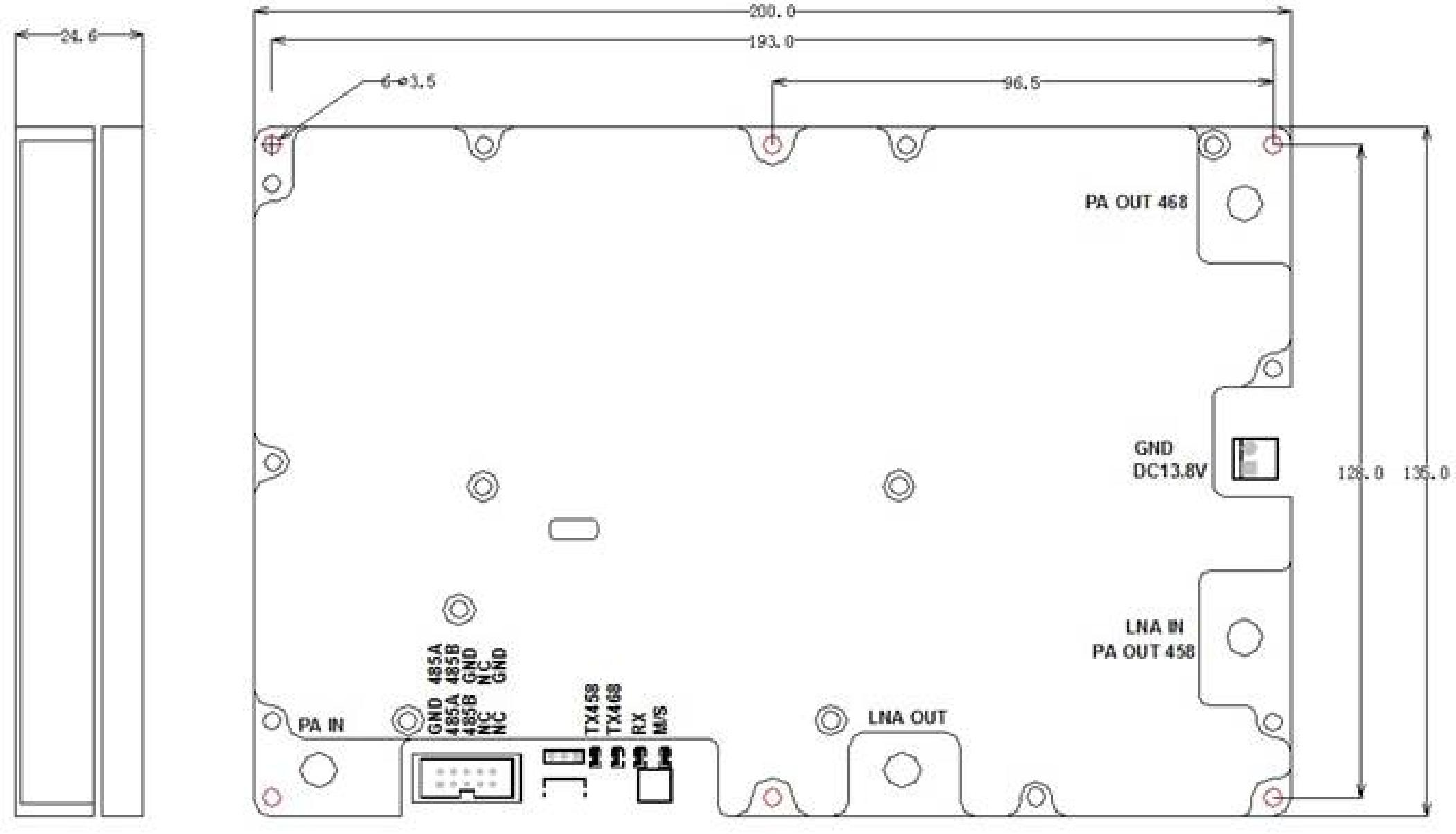
• The outline dimension drawing of the different frequency power amplifier is as follows: 10- pin monitoring connector with the notch facing outward.